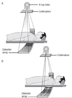
Until the 1990’s all commercial scanners contained may detector elements aligned in a single row
 |
| Single-detector row scanners have many detectors situated in an arc (third-generation) or a ring (fourth-generation). |
The single row design was used in both 3rd and 4th generation CT systems. In 3rd generation systems approximately 700 detector elements were arranged in an arc of the gantry. 4th generation systems used as many as 4,800 detectors in a single row arranged in complete ring. In scanner with a single detector row, each detector element is quite wide in the width or Z direction at approximately 15mm in size, and opening or closing the collimator controls the slice thickness by controlling the portion of the detector’s width that is exposed to the incoming xrays.
The width of the detectors (z axis) in a single detector array places an upper limit in slice thickness. Opening the collimation beyond this point would do nothing to increase slice thickness, but would increase both the dose to the patient and the amount of scattered radiation. Therefore, in these systems the largest allowable slice thickness is less than the detector width, usually 10mm. Fan beam is usually referred to the radiation emitted from the collimated xray source. Each gantry rotation produces data for a single slice.
Positioning Patient Anatomy
Calculating the area of patient anatomy to be covered during an examination with a single detector row, axial scan method is a simple process of mulplying the slice increment selected by the number of slices acquired. If slices are contiguous the slice increment will be equal to the slice thickness. For example, an examination protocol of the abdomen call for contiguous, 5 mm slices to be taken from the level of the diaphragms to the level of the iliac crest. In this case the collimator is opened to 5mm, and the table is moved 5mm after each gantry rotation. Using an AP localizer image to plan the study, 40 images would be required if the total width (z) distance to be scanned is 200mm (40 images x 5mm). For the sake of illustration, if the 40 slices were to be acquired using a 5mm slice thickness, but a 7-mm slice increment ‘skipping 2 mm of anatomy between each slice’, then the total distance from first slice to last would be 280 mm (40 images x 7mm).


No comments:
Post a Comment