Towne Method - Radiography
Anteroposterior (AP) Axial Projection
AP axial projection of the skull is most commonly known as Towne Method, angulation of the CR is not specified but degrees of flexion of the neck should be check to compensate the angulation of the central ray. Towne is also known as Citing Chamberlain Method. Before Towne demonstrate this technique many authors has already studied and described this technique but slightly different in varations. In 1912 Grashey put out first and demonstrated the description of AP axial projection of the skull or cranium. 1926, Altchul and Towne described the same position recommendation, with strong depression of the chin, the only is the central ray angulation and its direction. Altschul recommended 40° caudad CR angle and directed to foramen magnun. Towne (Citing Chamberlain) the CR is directed to mid-sagittal plane from a point about 3 inches above the eyebrow to the foramen magnum, and gave no specified CR angulation but of course, it also depends on the degree of flexion of the patients neck.Technical Factors:
Film Size - 10 x 12 inches, Lengthwise
kVp -70 to 80
mAs - 20
SID - 48 inches
Collimation : Four side of the Patient's head
Patient Position Towne Method:
Before positioning on patient be sure to remove all metal, plastic, or other removable object from the patient's head.| AP axial projection |
- Erect or Seated Erect or Supine position
- Center mid-sagittal plane to the midline of IR or grid.
- Put Patient's arm in a comfortable position
- Both shoulders lie in the same horizontal plane.
On hypersthenic or obese patient, position them in the seated upright position, to comfort patient and avoiding increasing in SID.
- Let patient lean back lordotically with shoulder resting against the vertical grid or cassette, to bring head closer to IR. If this position, patient cannot tolerate, a occipito-basal region may be taken using the PA axial projection or Haas Method. A reverse of the AP axial projection which also produce a similar and comparable radiograph.
Part Position:
- Depress chin, bringing OML perpendicular to IR. For patients unable to flex their neck to this extend, align the IOML perpendiculat to the IR. Add radiolucnet support under the head if needed. (See note)
- Align midsagital to CR and to the midline of the grid or table/Bucky surface.
- Ensure that no head rotation and /or no tilt exists.
- Ensure that the vertex of the skull is in x-ray field.
Central Ray:
- Angle CR 30 degree caudad to OML, or 37 degrees caudad to IOML. (see note)
- Center at the midsagittal plane 2 1/2 inches (6.5 cm) above the glabella to pass through the foramen magnum at the level of the base of the occiput.
- Center IR to projected CR.
- Minimum SID is 40 inches (100 cm).
Collimation:
- Collimate to outer margin of skull.
Respiration:
- Suspend respiration.
Note: If patient is unable to depress the chin sufficiently to bring the (OML) perpendicular to the IR even with a small sponge under the head, the infraorbitomeatal line (IOML) can be placed perpendicular instead and the CR angle increased to 37 degrees caudad. This maintains the 30 degrees angle between the OML and the CR and demonstrate the same anatomic relationships.
(A 7 degrees exists between the OML and the IOML.)
Radiographic Criteria:
 Structure Shown:
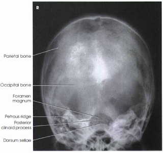
- Occipital bone, petrous pyramids, and foramen magnum are shown with the dorsum sallae and posterior clinoids visualized in the shadow of the foramen magnum.
Position:
- Petrous ridges should be symmetric, indicating no rotation.
- Dorsum sallae and posterior clinoids visualized in the foramen magnum indicate correct CR angle and proper neck flexion/extension.
- Underangulation of the CR will project the dorsum sallae above the foramen magnum, and overangulation will project the anterior arch of C1 into the foramen magnum rather than the dorsum sallae.
- Shifting of the anterior or posterior clinoids within the foramen indicates tilt.
Collimation and CR:
- Entire skull is visualized on the image with the vertex near the top, and the foramen magnum is in the approximate center.
- Collimation are to the outer margins of the skull. Because of excessive elongation of the facial mass, it is necessary to include this in the collimated area.
Exposure Criteria:
- Density and Contrast are sufficient to visualize occipital bone and sellar structures within foramen magnum.
- Sharp bony margins indicate no motion.


