
Image Artifacts on CT Scan
Image artifacts are defined as anything appearing on the image that is not present in the object that is being scanned. This artifacts have many different presentation and can be attributed to many causes. They can be broadly classified as physics based or resulting from the physical processes associated with data acquisition, patient based, or equipment induced. Artifact can seriously degrade the quality of CT scan images, sometimes to the point of rendering them diagnostically unusable. Recognizing various artifacts and understanding why they occur and how they can be prevented or reduced is an important aspect of image quality assurance. Recognizing the possible causes of artifacts can save a significant amount of time and money. Ideally, better identification of artifacts can permit them to be corrected without a service call; if the severity of the artifact requires a service engineer, the call can be placed promptly.
Any object seen on the image is not present in the object scanned is considered an artifact. A variety of sources cause this artifacts, and this are listed following below:
Beam Hardening
Beam hardening is the polychromatic nature of the xray beam used in CT scan and its effect on the creation of beam hardening artifacts. As an xray beam passes through an objects, lower energy photons are preferentially absorbed, creating a harder beam. Individual rays are hardened to differing degrees, and this variation can not be adjusted for by the reconstruction algorithm. A common clinical example of beam hardening occurs between the bones in the head, where streak artifact appear between the two bones on the CT scan image. The degree of beam hardening is dependent on the composition of the part being examine and the extend the beam must travel through various tissues. The beam is hardened more by dense objects like more by bone and less by fats. Two types of artifacts can result from this effect, cupping artifacts (the periphery of image is lighter) and the appearance of dark bands of streaks between dense objects in the image.
 |
| Beam hardening from the dense petrous bones creates low attenuation streaks in the image (arrows). |
How to minimize Beam Hardening Artifacts?
CT systems uses 3 feature to reduce beam hardening: by filtration, calibration correction and beam hardening correction software.
Filtering
Filtering the beam by metallic material such as aluminum filters out the lower energy components of the beam before they pass through the patient. An additional filter shaped like a bow tie is used for body studies to further harden the edges of the beam, which will pass through the thinner parts of the patient.
Calibration Correction
Scanners are calibrated in a range of sizes so that beam hardening compensation can be tailored to different parts of the patient. Like for example, a head scan field of view (SFOV) typically uses correction to reduce cupping artifacts often seen in the posterior fossa. Correction software that reduces beam hardening artifacts can also be included in bone or detail reconstruction algorithms. Raising the kVp will increase the average photon energy of the beam, therefore reducing beam hardening to some extent.
The best strategy available to the operator to avoid beam hardening is to select the appropriate SFOV to ensure the correct filtration, calibration and beam hardening correction software is used.
Partial Volume Artifact
Partial Volume Artifact can reduce image artifact in a number of ways. Recall that the partial volume effect occurs when more than one type of tissue is contained within a voxel. Although related, partial volume artifacts are a separate problem from that of partial volume averaging. One type of partial volume artifact occurs when a dense object lies to the edge of the FOV. This can result in the object showing up in only a small number of views collected from the tube 360 degrees path. On the image below, exaggerates the geometry of the xray beam to demonstrate how an object that lies to the periphery may not appear on all views. The inconsistencies between the views cause shading artifacts to appear in the image. The best method of reducing partial volume artifacts is to use thinner slices.
 |
| Partial volume artifacts can occur when dense objects lie to the edge of the SFOV and are only present in some of the views used to create the image. |
An adequate number of projections, as well as an adequate amount of data within each projection, must be available to reconstruct a CT image of optimal quality. Insufficient projection data ( for instance, when the helical pitch is greatly extended) is known as undersampling. Undersampling causes inaccuracies related to reproducing sharp edges and small objects and results in an artifact known as aliasing, in which fine stripes appear to be radiating from a dense structure. Because aliasing artifacts consist of evenly spaced lines they are easy to distinguish from anatomic structures and therefore, seldom do they render and image undiagnostic. However, when resolultion of the detail is important, aliasing artifacts can be combated by slowing gantry rotation speed (this could result in increase of scan time) or by reducing the helical pitch.
Edge Gradient Effect
The edge gradient effect result in streak artifact or shading (both light and dark) arising from irregularly shaped object that have a pronounced difference in density from surrounding structures. A common clinical example is artifacts that result when barium and air lie adjacent to each other in the stomach.
 |
| The irregular shading in the left lobe of the liver (indicated by arrows) in this image is caused by a combination of edge gradient effect and beam hardening. The artifacts arise from the pronounced difference in density between the air and barium in the stomach. |
Artifacts from the edge gradient effect are largely unavoidable, but are somewhat reduced by thinner slices. Using a low HU value oral contrast, such as Volumen, or water (a neutral HU contrast agent in place of a barium suspension can eliminate the streak artifacts from the gastrointestinal tract.
Motion
Motion Artifacts from patient motion typically appear as shading ghosting this mean that objects appear to have a shadow, streaking or blurring.
 |
| The diagonal shading degrading this image is caused from patient movement during the scan. |
Manufacturers have built features into the CT scan systems to reduce this motion artifacts such as over scan and partial scan modes, software correction, and cardiac gating.
Voluntary motion can be reduced or eliminated by adequate preparing the patient for the examination. Time is well invested in explaining the procedure to the patient, reinforcing the importance of remaining still, and confirming that the patient understands any breathing requirements. Positioning aids such as an angle sponge placed beneath the patient is more comfortable during the examination. In some situations, immobilization devices such as straps and wedge sponges can provide the patient additional stability. In some situations, particularly with pediatric patients, it may be necessary to immobilize the patient by means of sedation. Scanning the chest and abdomen using the shortest scan time possible also helps to minimize artifact from involuntary motion. Cardiac protocols often include pharmacologic methods to lower the patient’s heart rate in an effort to reduce motion artifact on the image.
Metallic Artifacts
 |
| Metallic hardware in the patient’s spine resulted in streak artifacts. |
Metal object in the scan field of view (SFOV) will create streak artifacts. They occur, in part, because the density of the metal is beyond the range of HU values that the system is designed to handle. The range of HU values that the system is designed to handle. The range of xray intensity values to which the scanner can accurately respond is called the dynamic range. The upper limit on older Ct systems was often 1000 HU – this dense cortical bone. Metal objects have attenuation values higher than 1000. Newer CT system has expanded the HU unit scale and can include of metallic streak artifacts. However, beam hardening, partial volume, edge gradient, and aliasing all contribute to the streaks that result from metal in the scan field of view (SFOV).
How to minimize Metallic Artifact?
The best way to reduce metallic artifact is to minimize the metal present in the scan field of view. Patients are asked to take off any removable metal objects such as jewelry before scanning begins. For body scans, patients should change into a hospital gown to avoid scanning zippers, safety pins, etc. for nonremovable items, such as dental fillings, prosthetics devices, and surgical clips, it is sometimes possible to angle the gantry to exclude the metal objects. When it is impossible to scan the requied anatomy without including metal objects, increasing technique, especially kVp, may help penetrate some objects and using thin sections will reduce the contribution caused by partial volume artifact.
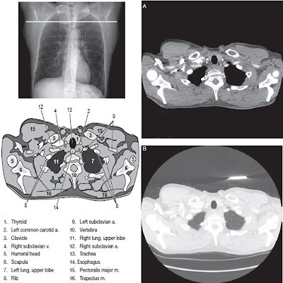
Out of field Artifacts
Out of field artifacts are caused by anatomy that extends out side of the selected scan field of view. These artifacts occur because the anatomy outside the SFOV attenuates and hardens the xray beam, but is ignored in the image reconstruction process. A common clinical example is when imaging of the body must be done with the patient’s arm down by their side, rather than raised out of the way of the scan.
 |
| Out-of-field artifacts can arise when portions of the object scanned lie outside the SFOV. Image (A) was taken with the patient’s arms down by his side, resulting in pronounced artifacts. The scan was repeated, and image (B) was taken after the patient’s arms were raised to lie outside of the scan field. |
If the arms are outside the scan field they will not be seen on the image, but their presence can lead to severe artifacts in the image. In addition, obese patients may obstruct the reference detectors, further contributing to image artifacts. Out of field artifacts appear as streak and shading on the image.
Out of field artifacts can be avoided when an scan field of view (SFOV) can be selected that is larger than the patient. For exceptionally large patients who exceed even the largest scan field of view (SFOV), out of field artifacts are inevitable. Encouraging patients to raise their arms out of the way of the scan field of view (SFOV) will also avoid artifact.
Ring Artifacts
Ring artifacts occur with 3rd generation scanners and appear on the image as a ring or concentric rings centered on the rotational axis.
 |
| Ring artifacts appear from a malfunctioning or miscalibrated detector element in a third-generation scanner. |
They are caused by imperfect detector elements – either faulty or simply out of calibration. In some instances radiologic technologist may eliminate circular artifacts by recalibrating the scanner. Should that fail, the problem must be reported to a service engineer for repair.
Tube Arcing
A common cause of equipment induced artifact occurs when there is a undesired surge of electrical current like a short-circuit, within the xray tube. This is referred to as either high voltage arcing or tube arcing. Arcing tends to occur whenever there is a large difference in electrical potential, such as the case between the anode and cathode in an xray tube. In a xray tube, arcing can occur through residual gas molecules present within the evacuated envelop of the xray tube. As an xray tube ages, the tendency to arc often increases owing to such factors as degradation of the vacuum within the tube, which results in increased gas pressure. Arcing can also occur through the oil in the xray tube housing. Once an xray tube starts to arc, a cascade -type effect may occur that sets event in motion that contribute to yet more frequent arcing. The arcing causes a momentary loss of xray output, which contaminates the xray signal collected at the detectors, affecting proper image reconstruction and hence producing artifacts. In the early stages the arcing may be infrequent, and small artifacts begin to appear in the images. However, as the tube ages further, resulting in images with more pronounced artifacts.
Helical and Cone Beam Effect
Helical scans can be affected by all of the artifacts explained so far. However, there are additional artifacts that can occur in helical scanning attributable to the helical interpolation and reconstruction process. The introduction of helical scanning necessitated new image reconstruction methods because now the table moved continuously during data collection and the view needed to reconstruct the images were not all in the same plane. To address these problems, interpolation methods used measurements from either side of the image plane to create each image. The interpolation can result in artifacts, particularly when anatomic structures change rapidly in the it width z direction. Higher pitches require more interpolation artifacts result in subtle inaccuracies in CT number and can be easily misinterpreted as disease. These artifacts can best be avoided by using a low pitch whenever possible.
The interpolation process becomes even more complicated as the number of detector rows increase. Windmill artifacts appear only on MDCT helical systems.


No comments:
Post a Comment