
Heart and Great Vessels MRI Scan
MRI of the heart and great vessels are usually done to
diagnose and study these common indications:
- Thoracic aortic aneurysm, dissection and coarctation.
- Complex congenital abnormalities of the heart and great vessels.
- Artial or ventriculat septal defect
- Assesment of ventriculat muscle mass.
- Vessel patency and thombus
- Valvular dysfunction
Equipment Needed
- Body coil volume torso array coil
- RC bellows
- ECG leads
- Ear plugs
Patient Positioning
The patient lies supine on the examination couch with the
RC bellows (if required) and ECG gating leads attached. If
breath-hold technique is not possible, respiratory gating or triggering is
recommended to reduce the respiratory artefacts. The patient is positioned so
that the longitudinal alignment light lies in the midline, and the horizontal
alignment light passes through the level of the fourth thoracic vertebra,
or the nipples. The patient can be placed feet first into the magnet if
the ECG trace is unsatisfactory to change the polarity of the patient
relative to the main
field of the magnet.
Suggested protocol
A three-plane localizer is optimal as the heart and
vascular structures of the chest lie obliquely within the cavity of the chest.
The images provided in three orthogonal planes provide a localizer so that
oblique views of the heart and great vessels can be prescribed.
Coronal breath-hold fast incoherent (spoiled) GRE/SE T1
Acts as a localizer if three-plane localization is
unavailable, or as a diagnostic sequence. Medium slices/gap are prescribed relative to
the vertical alignment light, from the posterior chest muscles to the
sternum. The area from the top of the sternum to the diaphragm is included
in the image.
 |
| Coronal SE T1 weighted image through the chest cavity demonstrating slice prescription boundaries and orientation for axial imaging of the heart. |
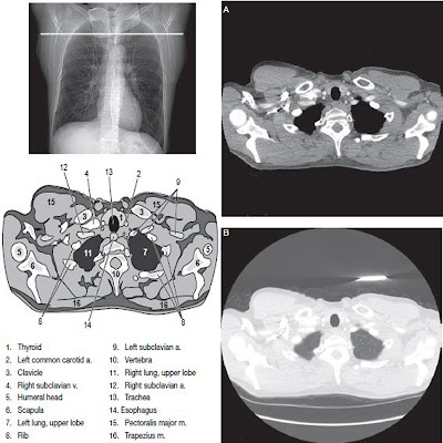
Axial SE/FSE T1
As for the Coronal T1, except slice thickness/gap is
altered to fit the ROI. Prescribe slices from the inferior border of the heart to
the superior aspect of the arch of the aorta
 |
| Axial T1 weighted FSE image of the chest using cardiac gating. |
Specific Cardiac Views
Long Axis view (two chamber): From the axial T1
projection, using a slice through the left ventricle, align the slice slab
parallel to the intraventricular septum and ensure the slab covers the whole of the left ventricle.
 |
| Axial FSE T1 weighted image showing slice orientation for the long axis view. |
 |
| Two chamber long axis view. |
Four chamber view: from the long axis view align through
the apex of the left ventricle and the mitral valve. Ensure the slice
slab covers the whole of the left ventricle. This plane can also be
acquired from the short axis view.
 |
| Long axis with slice orientation and slice boundaries for the four chamber view. |
 |
| Four chamber view. |
Short Axis view: from the long axis view align
perpendicular to the long axis view imaging plane so that the alignment is parallel
to the mitral valve. Ensure the slice slab covers the whole of the left
ventricle. The short axis plane can also be prescribed from the coronal localizer. A location can be identified on the
coronal localizer, posterior at the aortic root; and another on the coronal
by paging the slices anteriorally to the apex of the heart. Once these
locations are known, the short axis can be prescribed by explicitly
identifying the locations. The scanner will essentially draw an imaginary line
between the points and scan perpendicular to that imaginary line. The
four chamber view can also be acquired from the short axis view by
orientating the slice prescription through the left and right ventricles angled
parallel to the diaphragm.
Sagittal/oblique SE T1
As for Axial SE T1, except slices are angled through the
ascending and descending aorta and prescribed from one lateral edge of
the vessel wall to the other.
This sequence is used to visualize the ascending and
descending aorta in one view (candy cane or walking stick view). Select an
image from the axial series that demonstrates both portions of the aorta. Check
slice position on a more superior slice that demonstrates the arch.
Black blood imaging vs bright blood imaging
SE or FSE images are generally acquired with saturation
pulses for the evaluation of black blood. Gradient echo, PC or EPI
imaging sequences can be acquired with GMN for the evaluation of bright
blood. Other black blood imaging techniques utilize a modified
inversion recovery sequence, known as Double IR or Triple IR. Although the
various vendors have unique acronyms for these sequences, the premise is
the same.
In each case the sequence begins with one 180° RF pulse followed by another 180° RF (double IR). In this case the sequence has essentially been driven to equilibrium. Since flowing blood does not stay within the slice for enough time to experience both 180° RF pulses, flowing blood appears
In each case the sequence begins with one 180° RF pulse followed by another 180° RF (double IR). In this case the sequence has essentially been driven to equilibrium. Since flowing blood does not stay within the slice for enough time to experience both 180° RF pulses, flowing blood appears
black. In triple IR sequences, the double IR sequence has
an additional 180° pulse at the frequency of fat for spectral
presaturation. In this case, the suppression of epicardial fat combined with black
flow within the cavity of the heart, allows for better visualization of
the myocardium.
Oblique incoherent (spoiled) GRE T1 or coherent GRE T2* multiphase (cine)
Images of the heart, acquired during multiple phases of
the cardiac cycle provide cardiac images during the beating of the heart.
This technique is known as multiphase imaging. The more slices acquired
within each cardiac cycle, the better the temporal resolution
(resolution over time). For cardiac imaging temporal resolution, particularly in
multiphase imaging, is limited by scan time. For example, if 16 phases of the
cardiac cycle are to be acquired during one phase of the cardiac cycle
this means that these images are acquired at the same slice location, but
at different times
during the cardiac cycle R–R interval. Cardiac cine (like multiphase imaging) is used to assess
cardiac function. The most common views for cardiac cine images are the
short axis view or the straight axial view of the chest. This view
is generally used to evaluate the left ventricle. For other areas of the
heart, two chamber or four chamber views may be utilized. Two chambers are
best demonstrated on a sagittal/oblique view, four chambers in the
coronal/oblique plane. Additional views such as the left ventricular outflow
technique may also be useful. Medium slices/gap are prescribed in the plane relevant to
the ROI (often axial or oblique). Select the cine functions as
appropriate to the system, i.e. number of slices and phases per acquisition


No comments:
Post a Comment